While some of the changes we’ve seen have been quite dramatic, like the Mercedes sidepods, other modifications have been more subtle and offer us some insight into how teams feel their 2022 cars are performing.
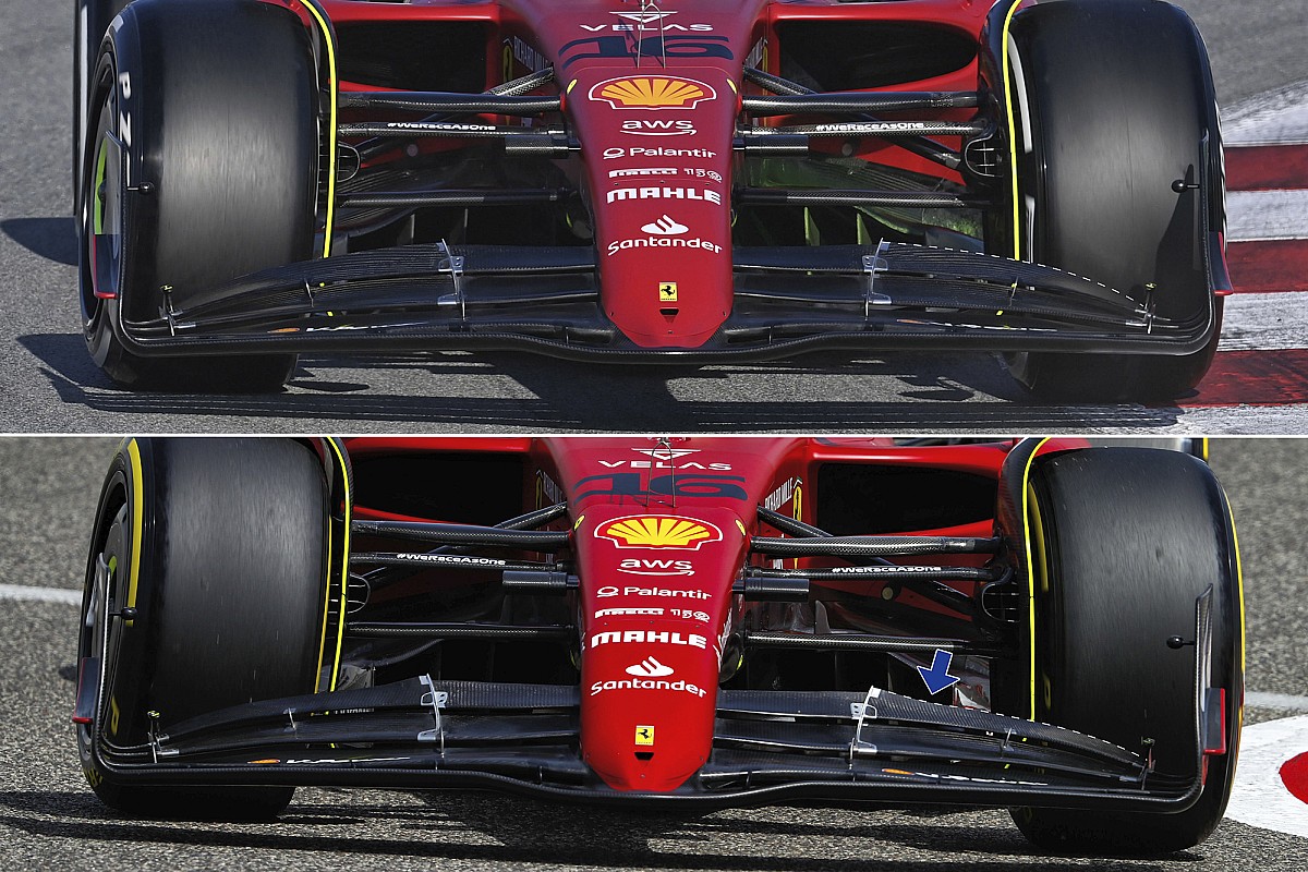
Ferrari made a small change to its front wing arrangement between the first and second test, as it appears that the team feels that just adjusting the flap angle wouldn’t be enough to balance the difference in downforce required for the two venues.
This difference can be seen near the inboard flap adjustment pivot, with some of the flap’s trailing edge cut away in order to alter the proportion of downforce being generated in the central portion of the wing (blue arrow).
Despite Mattia Binotto suggesting that the car wouldn’t change much between the two tests, the front wing wasn’t the only new specification part to adorn the F1-75 as the team performed some corrective surgery on the car’s floor too.
Ferrari F1-75 sidepod detail
1/2
Photo by: Uncredited
Ferrari F1-75 and McLaren MCL36 floor comparison 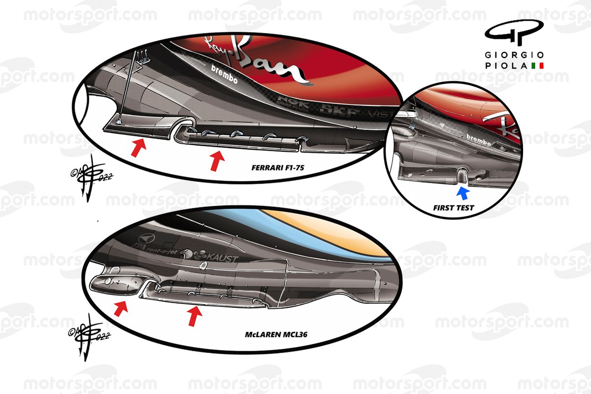
2/2
Photo by: Giorgio Piola
At the front, there was an interesting adjustment to the leading edge of the underfloor tunnel, with the innermost strake extended upwards over the top of the floor’s leading edge (blue arrow), which is a solution we’ve seen elsewhere, such as on the Williams FW44 and Haas VF-22.
And, whilst it had already made moves to change its floor at the first test (right image, right inset), making a cut out in the floor’s edge and introducing a tongue-like winglet that was housed within, it presented a solution similar to McLaren’s at the second test.
Both solutions take advantage of the floor cutout and edge wing regulations, with the latter of those two connected to the edge of the floor with a series of metal support brackets. These brackets are also oriented to help influence the local flow direction.
Meanwhile, the segmentation of the floor also means that different parts of the floor are loaded differently as the downforce builds and the car is pulled towards the track’s surface. This is where teams are expecting to make performance gains and also mitigate some of the ill effects posed by porpoising.
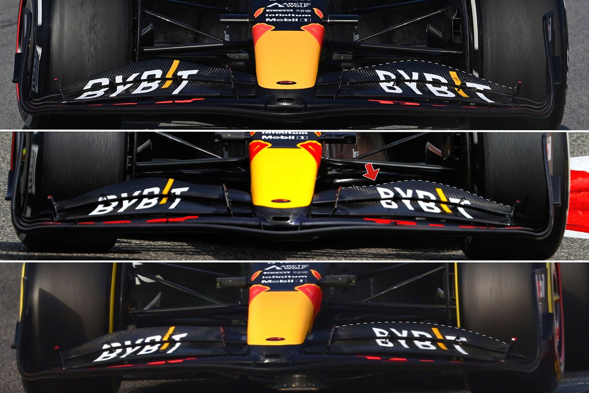
Red Bull Racing RB18 front wing comparison
There’s obviously a lot of difference between the Red Bull front wing and Ferrari design, but the two teams did make similar changes to the upper flap between the two events, with the trailing edge of the upper flap cut down near the inboard adjustment pivot (red arrows).
However, the introduction of a new front wing upper flap design (bottom) coincided with the arrival of its new sidepod solution on the last day of testing.
As can be seen from the dotted lines, the more centrally loaded design gave way to a more gradual curvature, which is mirrored in the redesign of the flap below too.
In terms of the sidepods, the new design variant takes what had already been considered as one of the most aggressive solutions and goes even further.
The change completely overhauls the bodywork’s shape, with the green lines on the images below providing insight into how this has resulted in the forward portion of the pod being sloped more steeply, whilst also providing an undercut that bleeds into its midriff and provides more space for the floor.
Red Bull Racing RB18 sidepod comparison 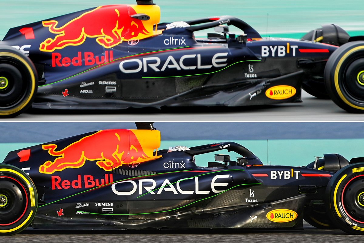
1/2
Red Bull Racing RB18 sidepod comparison 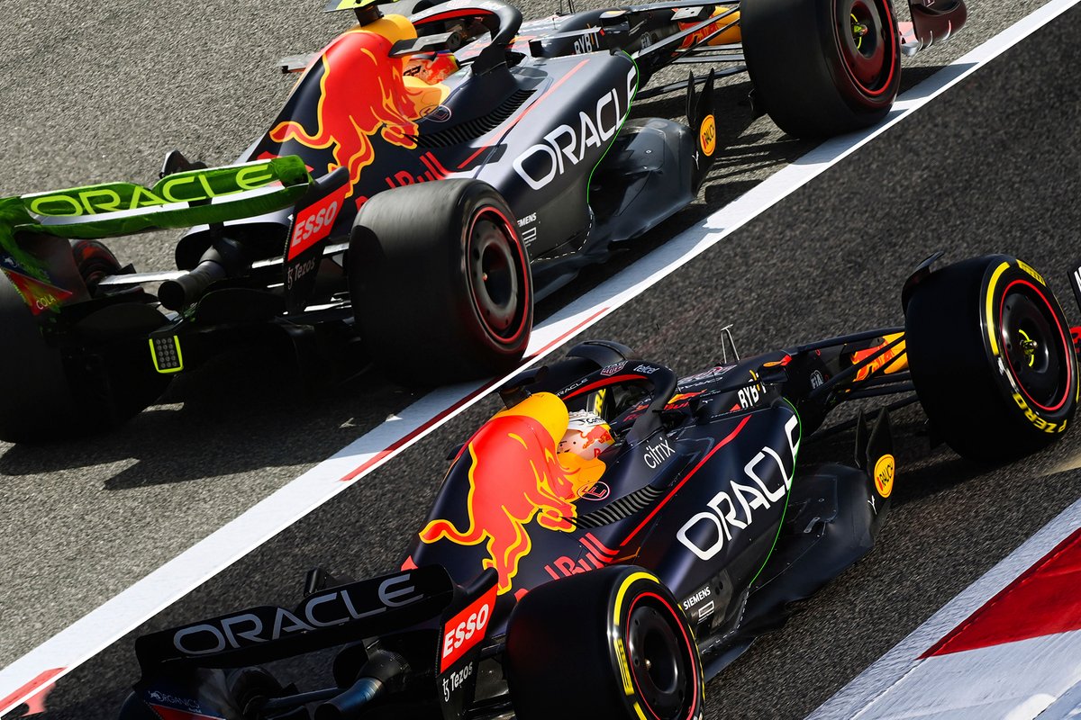
2/2
The steeper slope in the forward section is married to the changes made to the sidepod’s upper surface, with two sections having been created that help to define the path taken by the airflow towards the rear of the car.
The forward, more steeply sloped section, draws the airflow down towards the floor, whilst the upper slope has also been altered to correct how it draws the airflow down into the coke bottle region at the rear of the car too.
This is further aided by the revision made to the diffuser kick region (red arrow), which has a two-fold effect.
It not only changes the airflow’s behavior on the upper surface, which is critical to how the airflow is drawn into the gap between the tire’s sidewall and diffuser and the coke bottle region, but also in how the airflow transitions in the underfloor tunnel and the diffuser .
The Mercedes front wing has also been fettled during its pre-season adventures in Spain and Bahrain, with the downwardly curved inboard profiles attached to the nose (top, Barcelona) being inclined in order to produce more downforce (blue arrow, middle).
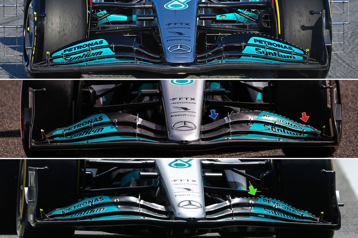
Mercedes W13 front wing comparison
The design of the upper flap was also altered to create a pronounced juncture that kicks up near the adjuster (red arrow, middle), likely in order to help more clearly define the outwash portion of the wing and improve flow across the front face of the tyre.
Mercedes also went on to play with the trailing edge of the upper flap, as we’ve seen from Ferrari and Red Bull, with the element being flattened-out in the inboard section near to the adjustment pivot (green arrow, bottom)
However, struggling to find the kind of performance that it was expecting from the W13 having fitted its new sidepod solution at the start of the second test, Mercedes also tried some more extreme setups towards the end of the test.
One such example can be seen below, where the team not had not only cranked the front wing angle up but also cut down the innermost strake in the underfloor tunnel.
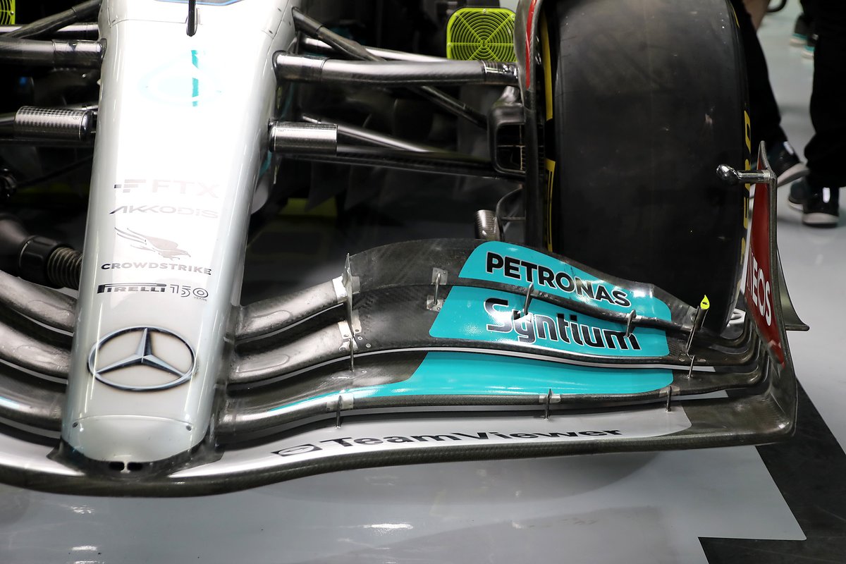
Mercedes W13 front wing detail
Photo by: Giorgio Piola
This obviously alters the effect that the strake has on the airflow’s passage, with the strakes performing a similar outwashing role that the bargeboards that preceded them produced.
As a result of these ad-hoc alterations, it’s also worth considering the other changes Mercedes made to its car at the second test, with the floor edge high on that list.
Having deployed a wave-like design during the first test, the introduction of the new parts saw Mercedes switch tact for Bahrain, with a more conventional flat edge deployed, exposing the trail edge of the strakes as they fan out to the floor’s edge (red arrow, below).
It’s likely we’ll see further developments in this region, as it tries to create the right kind of aerodynamic handshake between the various surfaces and how they influence the airflow around them.
Furthermore, Mercedes, along with several other teams, was forced to add metal support stays at the rear of the floor (blue arrow) in order to prevent the floor from flexing too much and help combat the effects of porpoising.
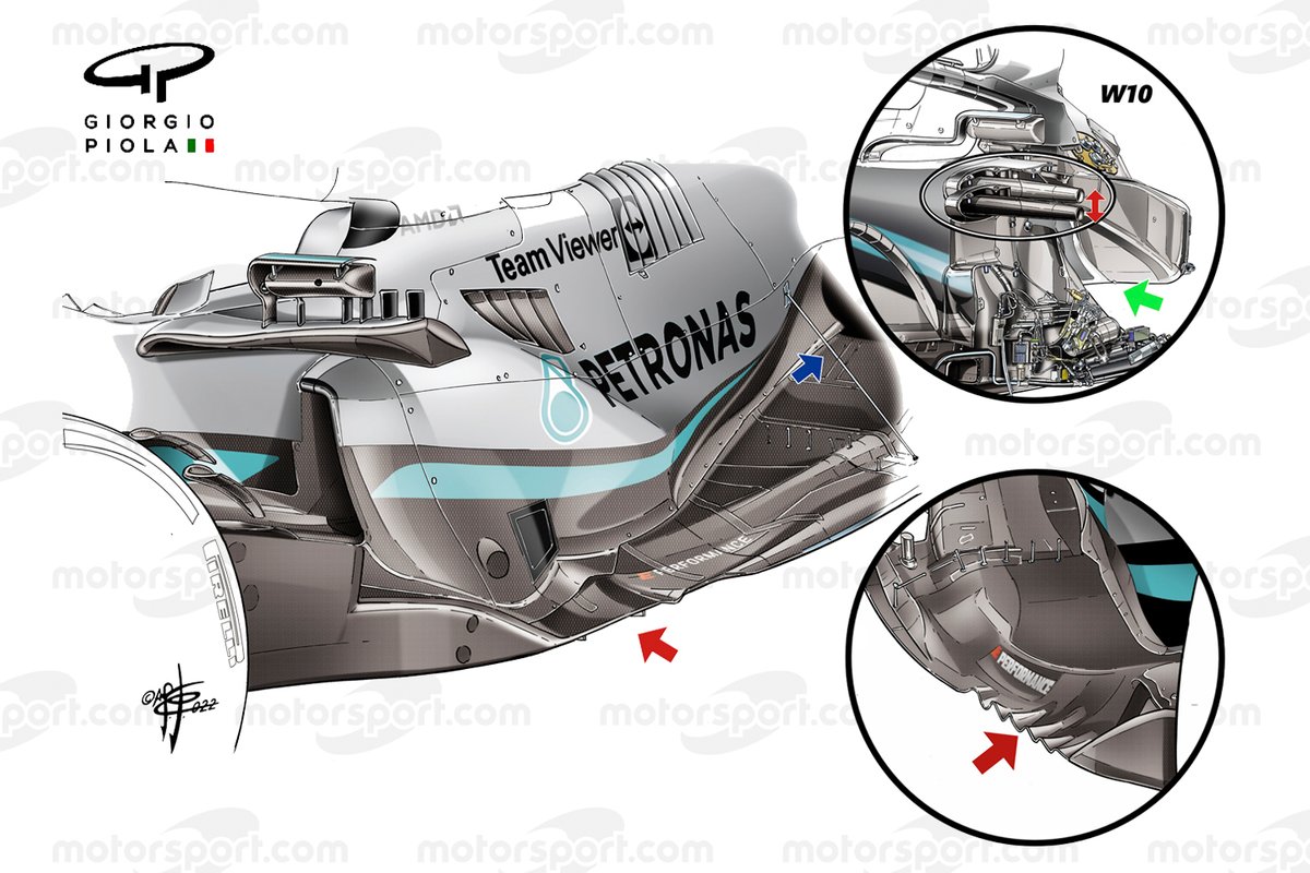
Mercedes SIS and floor comparison
Photo by: Giorgio Piola
The Mercedes sidepods or ‘zeropods’ as they have been commonly referred to, were one of the most talked about upgrades of the second test and for good reason, as it was yet another very different interpretation of the new regulations.
Whilst it appears that the sidepod has been shrunken quite dramatically, the inlet’s cross section is largely the same, albeit turned through 90 degrees from what we consider to be the conventional orientation.
This obviously allows the team to create a very narrow, sloping section of bodywork thereafter, but it also means that the inlet sits on top of the floor, rather than having the flow conditioning undercut we’re used to seeing.
This is all made possible by the way in which Mercedes has approached the placement of the side impact structures (SIS), with the uppermost the most important decision here, as that has implications on how you design the rest of the sidepod.
This upper SIS can be placed anywhere between 460mm and 550mm from the reference plane (the bottom of the car) and between 475mm and 525mm longitudinally from the front axle.
The height from the reference plane is critical here, as the lowest mounting point is 50mm higher than in 2021, which is part but not all of the reason why teams have shifted from the low-slung solution pioneered by Ferrari in 2017 and subsequently copied by everyone in the field since.
This alone meant that all of the teams had to rethink the upper SIS’s location and its impact on the sidepod’s design.
In Mercedes’ case, it decided to take a similar approach to previous years by considering the SIS as a means to deploy a flow conditioning device.
However, its SIS is mounted near the upper perimeter of the bounding box, rather than being at the bottom as had been the case over the last few years and is essentially a reversal of what it did with the W10 in 2020 (inset).
It’s also worth noting that the cross-sectional chassis trick used by Mercedes for a number of years is also key in the implementation of this design.
Whilst others could potentially follow suit if they believe there to be a tangible performance benefit and it works with their SIS placement, the radiators housed within the W13 are recessed as seen on the W10 (green arrow, upper right inset).

